
Roof truss problems don’t happen out of nowhere. They trace back to small gaps in execution that go unchecked. When left alone, those gaps turn into safety risks, costly delays and rework that sets a project back.
Tighter execution from the start is how pros avoid them.
How Trusses Are Designed
Wood trusses are engineered using specialized design software, most commonly developed by metal plate manufacturers within the truss industry. These programs have matured considerably over the years, giving designers a reliable picture of how a truss will behave once it’s in the structure.
Metal-plate-connected wood trusses are engineered and fabricated under ANSI/TPI 1, the national standard that governs truss design responsibilities, quality criteria and bracing requirements.
Designers apply structural loads based on the truss’s intended use, geometry and performance requirements. That includes dead loads, live loads and environmental loads (snow, wind and seismic) drawn from the applicable building code and geographic location. They also consider bearing locations, spans between these supports and any design elements of the building that may induce unique loads on any of the trusses.
When the trusses are manufactured prior to delivery, they are fabricated using 2x wood lumber laid out in a specific pattern to accommodate all of these incoming loads, then joined by metal plates pressed onto both sides of the truss. Each truss is then assigned an alphanumeric identifier that is reflected on a layout plan for the builder to follow.
The truss’s job is to carry those loads and transfer them to designated bearing points: typically walls or beams that pass the load down through the structure to the foundation. Equally important to the obvious downward loads are the lateral loads and uplift loads.
Getting these load paths right, including the connections between components, is fundamental to how the whole system performs. It’s also where problems are most commonly missed.
Causes of Truss Connection Issues
Most truss connection problems trace back to the same short list: misjudged loads, inconsistent fastening, rushed installation or a load path that was never clearly defined. Add snow, wind or shifting materials, and something has to give.
Load Miscalculations
Load miscalculations are one of the most common and least visible causes of roof truss complications.
When trusses or connections underperform in the field, incorrect loading assumptions during design are often the reason. Every structure is designed to the code-prescribed loads for its region — snow, wind and seismic values based on the applicable building code and local geography. If this is done incorrectly, the connection could possibly not be sized for the load it actually has to carry.
Snow loads, wind exposure and weight redistribution across interior walls are all easy to underestimate. When the load path isn’t properly accounted for, connections get overstressed. Without the right hardware or fasteners in place, that can mean cracked drywall, a warped frame or worse.
Improper Fastener Selection or Placement
Toe-nailing is still common on job sites, and code tables do publish allowable toe-nail capacities for certain loading conditions. The real risk is consistency: actual field capacity depends heavily on nail angle, depth and spacing, and small deviations can put a connection well below its tested value.
In moderate-to-high uplift or wind-exposure conditions, a rated connector or structural fastener removes that variability and is the more reliable choice.
Hurricane ties can be installed on either the interior or exterior face of the wall, and both are used in the field. Exterior installation has an advantage in high-wind regions: the wall sheathing sits directly behind the tie and backs up the connection against top-plate roll — the tendency of the top plate to twist or rotate under uplift when the connector isn’t otherwise restrained.
Interior installation is common and code-acceptable, but without that sheathing behind it, the joint has less resistance to roll under uplift if anything else about the connection is marginal.
More contractors are weighing structural screw systems like FrameFAST against traditional straps and ties for exactly this reason — the right screw system can replace the need for a tie altogether and sidestep the tradeoff entirely.
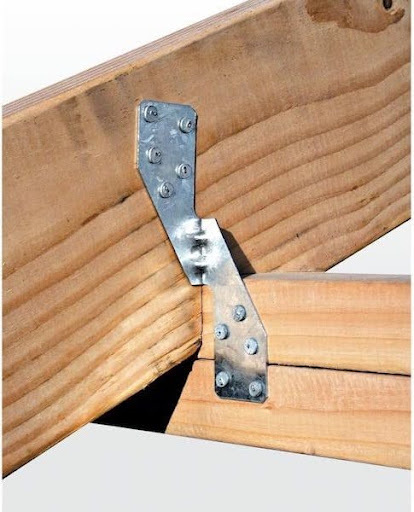
Where truss loads are intended to be fastened over non-load-bearing walls, traditional truss clips and metal hardware present their own challenges. These clips are designed specifically for alignment control on non-bearing walls, with slotted holes that allow the truss chord to move vertically under load.
Installing individual metal clips with hand-driven nails or nail guns on high ladders is physically demanding and difficult to do consistently, and manufacturer instructions typically call for clips on both sides of the truss to hit rated capacity in both directions — that can be easy to miss in the field.
An improperly seated clip in these locations is one of the more annoying post-installation problems to track down; it shows up as squeaking or friction long after the job is done.
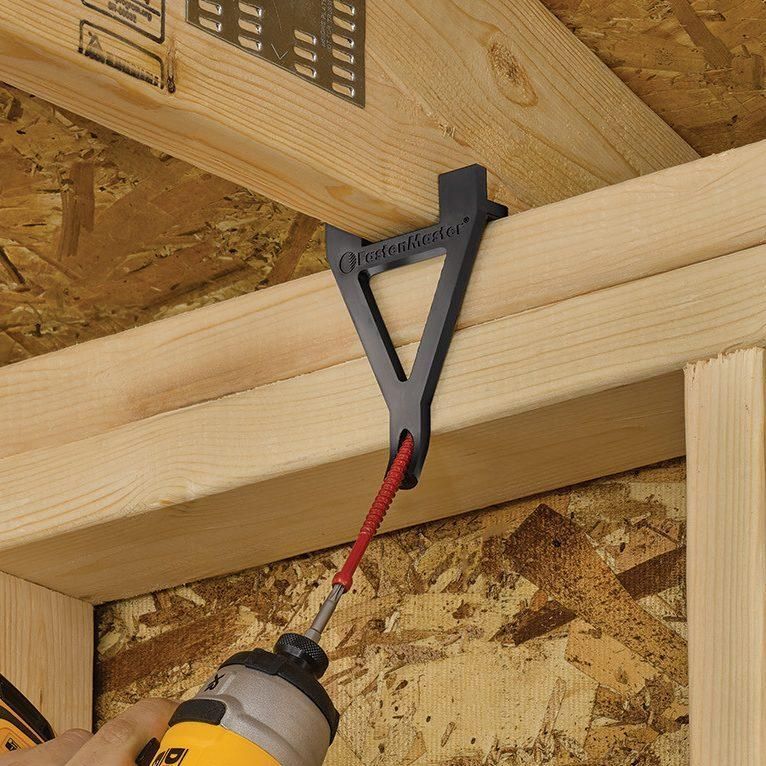
Engineered screw systems with integrated sleeves that allow for vertical movement, such as the FastenMaster NLB Fastener, have far better performance and make consistent installation easier, especially in tight or critical joints where a missed connection is hardest to catch and most likely to matter.
High-Risk Truss Connections
Some parts of a framing system carry more stress than others. They represent the places where forces converge and where small errors have big consequences. Because these critical spots aren’t always obvious, they tend to get rushed, especially when they are repetitive or awkward to reach.
Connections made at bad angles, in poor visibility or simply too fast are more likely to become a problem. With large trusses being set by crane and temporarily braced, it’s easy for alignment or fastening to drift slightly. Those small deviations can eat into structural capacity without showing up until the building is fully under load.
Sequencing matters, too. A connection can be perfectly designed on paper, but if it’s installed before the truss is fully seated or braced, issues will occur. Once the load reveals the problem, the connection is already buried in the wall.
Working from a ladder only makes this worse. It’s harder to drive fasteners accurately from an unstable position, and crews under time pressure will take shortcuts that aren’t visible until later.
Heel, Ridge and Web Connections
Heel connections, where roof loads move into the wall system, manage load transfer from the roof to the walls and don’t necessarily need to be complex. Tight alignment isn’t required to keep the load path intact. Many contractors are now weighing the benefits of advanced screw systems against traditional metal straps.
Ridge connections handle compressive forces at the peak. Misalignment distributes loads unevenly across the truss system and creates problems downstream.
Web connections hold the truss’s geometry together. A loose or poorly fastened web joint allows the truss to deform under loads, pushing forces into areas that weren’t designed for them.
Bearing Wall Connections
Truss design drawings show reaction forces at every bearing point, but under ANSI/TPI 1, the truss designer’s scope generally ends at the truss itself — the connection from truss to bearing wall is typically the responsibility of the Engineer of Record or building designer.
That handoff is where things get missed in practice: if the reaction values aren’t carried forward correctly into the connection design, the fastener spec can be wrong even when the truss itself was engineered correctly. Those values drive the selection of fasteners or connectors used to attach the truss to the supporting wall or beam.
Bearing wall connections are among the most structurally significant connections in a building. They resist the uplift and lateral forces that wind and seismic events create, and they keep the load path intact when it matters most. When they fail during a major event, it is never a minor repair. The consequences can include serious structural damage or total collapse.
A few things to get right when selecting and installing these connections:
- Load capacity: The uplift resistance of the fastener or clip needs to meet or exceed the reaction force on the truss drawings. Manufacturers publish this data, so be sure to use it.
- Fastener installation: Angle and placement matter. Most manufacturers offer specialized installation tools to help crews hit the required specification consistently in the field. Some installation tolerance is typically allowed, but always refer to manufacturer guidelines rather than guessing.
- Clip installation: Common issues here are the wrong fasteners, missing fasteners, damaged connectors and misalignment. All of them are avoidable with a checklist and a second set of eyes.
Non-Load-Bearing Wall Connections
Trusses are designed to transfer their load to structural walls, beams or other designated bearing points. Most buildings also have non-load-bearing walls that exist solely to divide space and are not intended to carry vertical loads.
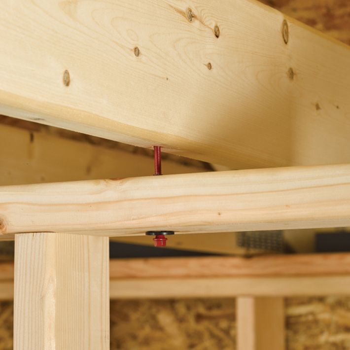
The problem comes when a non-load-bearing wall is framed tightly against the underside of a truss and fastened directly to it. That wall becomes load-bearing by default. The load path changes, and the symptoms show up as cracked drywall, uneven or sagging floors or unintended load transfer to a wall that wasn’t designed for it.
The fix is straightforward in principle: leave a gap between the top of the wall and the truss or joist above. That gap prevents the truss from passing unintended loads into the non-load-bearing wall and changing the load path. The harder part is securing the wall laterally without accidentally reintroducing vertical load transfer.
Two approaches work well:
- Specialty fasteners: FastenMaster’s NLB (Non-Load-Bearing Fastener) maintains the required gap, provides lateral connection capacity and eliminates the noise issues that come with metal clips.
- Slotted or deflection clips: These allow vertical movement while holding the wall laterally, but they’re more involved to install and can squeak over time from metal-to-metal contact.
Prevention and Best Practices
Good truss installation doesn’t leave room for guesswork. The design needs a clear load path, and the installation should follow it for every connection, every time.
In practice, that means:
- Confirming layouts before trusses go up
- Bracing every truss during the set exactly per the truss design drawings and SBCA’s BCSI guide — improper or missing temporary bracing is one of the most common causes of in-field truss failure, independent of fastener choice
- Not treating any connection as routine
Working from stable positions helps, too. Crews at height or in awkward spots are more likely to cut corners, and shortcuts in framing don’t announce themselves until something fails. SBCA’s step-by-step truss installation guide is a solid field reference for a full installation checklist.
Approved Connectors and Fasteners
Every connection needs hardware rated for what it actually has to handle, whether that’s uplift, shear or combined forces. That means selecting the right connector, installing exactly to spec and choosing compatible fasteners that reach full capacity.
Swapping products, skipping fasteners or placing them incorrectly all reduce performance, even if the hardware itself is good.
The FrameFAST™ system addresses many field reliability problems that come with traditional clips. It lets builders fasten top plates to trusses from the ground, which takes workers off ladders and removes the fall or ricochet hazards that come with overhead nailing.
In FastenMaster’s field testing that compared FrameFAST to traditional hurricane tie installation, FrameFAST reduced installation time per connection by roughly 80%. Results reflect ground-level installation vs. ladder-based tie installation and may vary by crew and site conditions.
The FrameFAST screw drives that system with a heavy-duty structural fastener rated for trusses, wall studs and deck joists. It’s code-compliant and drastically shrinks the margin for field errors.
Using hardware designed for foolproof installation means fewer mistakes, ensuring the building performs exactly as engineered once it’s under load.
Make Every Connection Count With FastenMaster
The difference between a connection that holds and one that doesn’t often comes down to the fastening system.
FastenMaster’s American-engineered solutions are built for consistent, precise installation, so the framing performs the way it was designed to when it matters most.
Don’t leave your connections to chance. Explore our framing solutions to find the right fit for your next project, or talk to one of our pros for a custom recommendation.